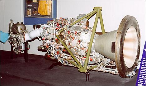
X-15 Engine at the US Air Force Museum at Wright Patterson AFB, Dayton Ohio

The XLR99 was the first large, "man rated," throttleable, restartable liquid
propellant rocket engine. The throttle setting could be varied from about 25 percent to
100 percent of thrust, and the restart capability allowed it to be shut down in flight
with the assurance that power would again be available later, if needed. The XLR99 was
one of the rocket engines used in the X-15 manned research aircraft which was
capable of propelling man to the fringes of space.
Developed and built by Reaction Motors Division of Thiokol Chemical Company, the
XLR99 could deliver up to 57,000 lbs. of thrust, or the equivalent of about 500,000
horsepower. The propellants for the XLR99 were liquid oxygen (LOX) and anhydrous
ammonia, fed into the engine by turbine pumps powered by hydrogen
peroxide at a flow rate of more than 10,000 lbs. per minute.
The XLR99 engine had a rated operating life of one hour, after which it could be
overhauled and used again, though operating times twice that long were demonstrated
in tests. Since the basic X-15 carried fuel for about 83 seconds of full-power flight,
and the X-15A-2 carried fuel for more than 150 seconds of full-power flight, each
XLR99 was theoretically capable of between 20 and 40 flights before overhaul.
In common with other large scale liquid fueled rocket engines, the walls of the XLR99's
thrust chamber were constructed of hollow tubing so that fuel could be routed through
the tubes to cool the chamber walls before being burned in the engine. The basic
weight of the engine is 910 lbs.
How the X-15 Engine Works
How does the engine start?
- Recessed in the center of the main chamber is a three-stage igniter. The first stage uses a fancy spark plug to light some fuel and start the fire. This is inside a larger chamber and that starts to burn and again we have a third chamber and that produces a really good fire. Once this is burning, the control system knows that it is ok to start the main chamber.
The main chamber.
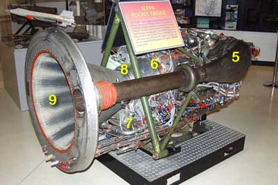
- The chamber, throat and nozzle or cone is either double layered or made of tubing welded together. Fuel (liquid ammonia) is pumped through this system to keep the metal cool enough so that it doesn't melt. If you look in the back of the engine you can actually see that it is made with a lot of tubing. It also has a ceramic coating to help protect it.
Then what.
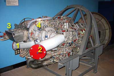
- Coming in to the engine is two large white pipes that are connected to the propellant tanks. One is the fuel, liquid ammonia and the other is the oxidizer, liquid oxygen. Remember that in space there is no air so we have to bring our own oxygen if we want to burn something.
- These two go through connected turbine pumps to force them in to the engine through what looks similar to a large shower head around the igniter. The oxidizer is sprayed out near the center and the fuel near the edges. This helps keep the greatest heat in the center of the flame to protect the engine.
The throttle.
- So far we have what looks like a normal rocket engine but here is where it gets interesting. Between the two big white pipes would normally be a stainless steel sphere about the size of a basketball. This sphere or tank contained hydrogen peroxide (H2O2) under high pressure. When H2O2 is exposed to a catalyst like silver, it brakes down into hydrogen and water. This chemical breakdown produces a huge volume of very hot steam. By feeding the peroxide through a silver screen we can produce the pressure and volume that is needed to turn the turbine to pump the propellants in to the rocket engine.
- Simply controlling the flow of peroxide determines the speed of the turbine and the flow of propellants in to the rocket engine and the amount of thrust that the engine will produce.
- The exhaust from the turbine is the large dark pipe on the side and exits out the back.
So, what is all the extra stuff for?
- The engine is covered with sensors and switches that are connected to a briefcase sized box underneath that is actually a basic computer built completely with relays. The box controls the startup sequence and monitors run time conditions. If any of the engine's conditions are not what they should be then the box switches to the shutdown sequence and purges all propellants out of the engine with nitrogen.
- There are also a lot of fittings that were used during engine testing but not during actual
use in the aircraft. Just for an example, you can see two fittings between 7 and 8 on the top
and bottom of the turbine exhaust that were used for exhaust gas temperature thermocouples only
during testing.


1. Fuel Manifold (liquid amonia)
2. Oxidizer Manifold (liquid oxygen)
3. Turbine pump speed control
4. Turbine pump
5. Turbine exhaust
6. Main chamber
7. Control box
8. Throat
9. Nozzle or cone, main exhaust
PDF Documents
- X-15 Hydrogen Peroxide Rocket Engine Reaction Control - Doc 89235main_TF-2004-16-DFRC
- X-15 Operational Experience with X-15 Hydrogen Peroxide Rocket Reaction Control Systems
If you have any questions, please Email


